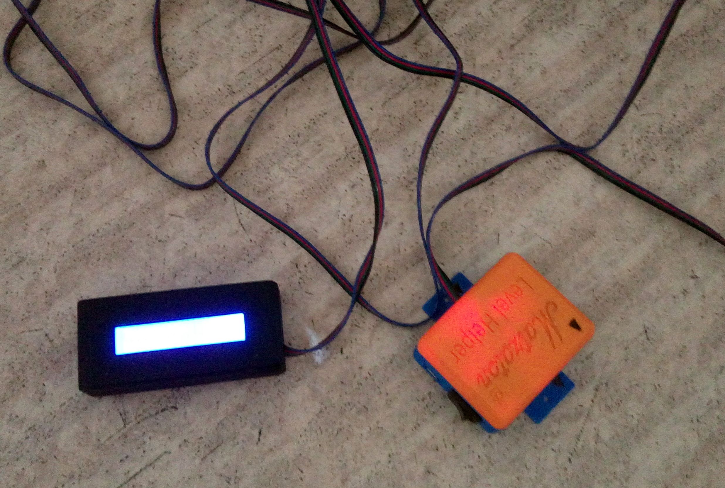
Matzaton Level Helper
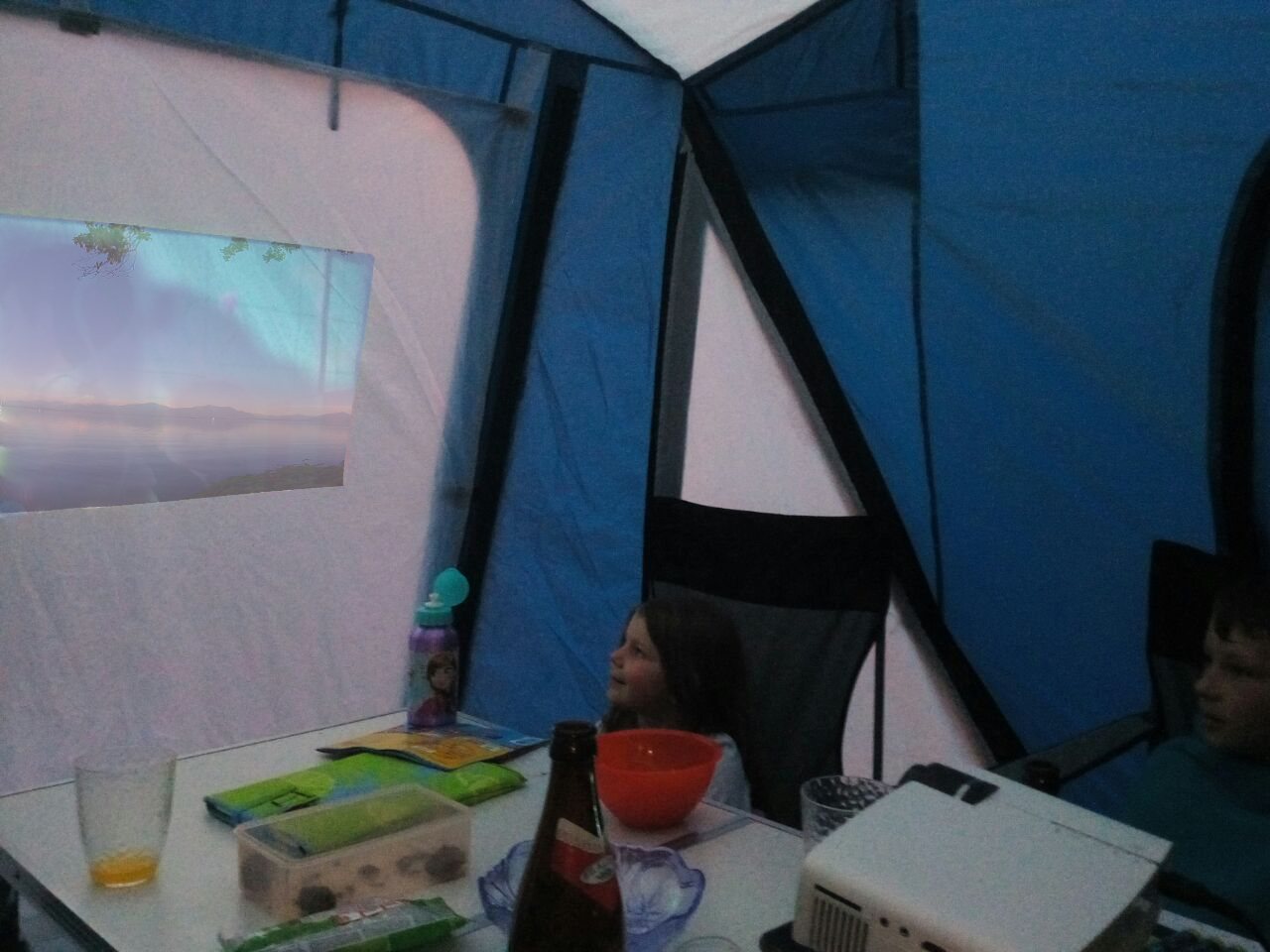
Der Matzaton Level Helper wird einfach entweder mobil auf den Boden im Wohnwagen gelegt, oder kann fest z.B. im Küchenunterschrank installiert werden. Es ist darauf zu achten, dass die Pfeile auf dem selbst gedruckten Gehäuse exakt nach vorn zur Kupplung zeigen. Das Display kann dann mit dem Kabel nach draußen genommen werden.
Was wird alles benötigt?
1x Arduino Nano ca. 4,-€
1x MPU 6050 3 Achsen Gyro Modul ca. 2,-€
1x LCD Display mit Shield 1602 ca 5,-€
1x Gehäuse für Arduino Nano (3D Druck) Link ca. 1,-€
1x Gehäuse für das Display (3D Druck) Link oder unser modifiziertes Link ca. 1,-€
1x 9V Blockbatterie ca. 1,5-€
1x Stromabnehmer für 9V Block ca. 0,5€
1x kleiner Schalter (Position selbst im Gehäuse suchen und eine Aussparung bohren. Schalter ist aber nicht nötig, wenn ihr die Batterie jedes Mal nach Benutzung selbst wieder entfernt.) ca. 1,5€
1x 4-adriges Kabel (Wohnwagenlänge mit Deichsel plus 3 Meter) ca. 9,-€
+diverse kurze farbige kleine Kabel (Jumperkabel eignen sich besonders). ca. 0,5€
Gesamt ca. 26,-€
Plus zur Programmierung einen Computer und die Arduino IDE. Link
Als Erstes druckt ihr euch die Gehäuse aus (am besten mit ABS, da im Wohnwagen ggf. Temperaturen über 60 °Celsius herrschen und PLA da zu schmelzen beginnt).
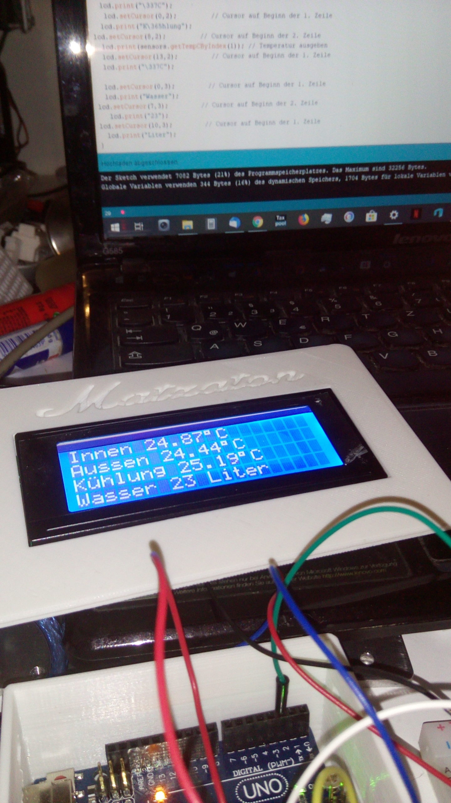
Dann schließt ihr den Arduino an euren PC per USB an und startet die Arduino IDE. Öffnet das hier Link zum Download bereitgestellte Sketch in der IDE und ladet es auf den Arduino. Wenn alles erfolgreich geklappt hat, trennt den Arduino wieder vom PC.
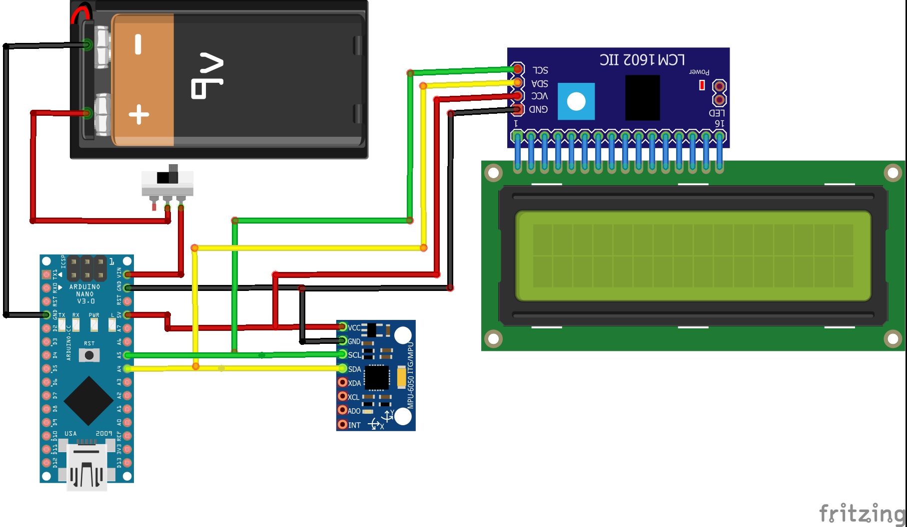
Dann lötet ihr die Kabel an den Arduino (Schema beachten!)
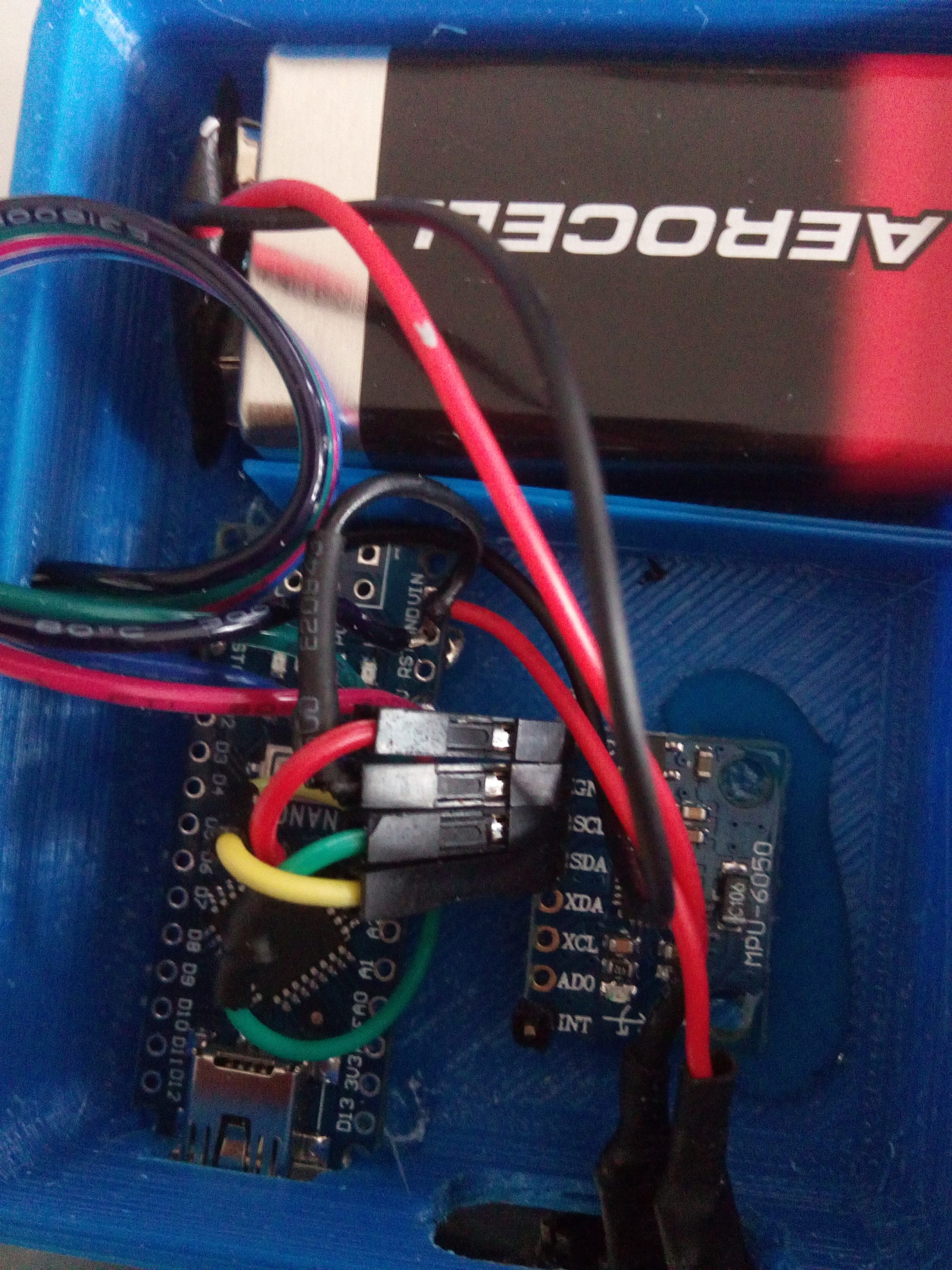
Anschließend die Kabel an den MPU-6050 löten oder Stecken mit Jumperkabeln.
Ist das erledigt, die Kabel an das Display anlöten. (Achtet beim Display wie auch beim Arduino darauf, dass ihr die Kabel vor dem Löten durch die Öffnungen im Gehäuse zieht!)
Sind alle Kabel an der richtigen Stelle verlötet, benutzt etwas Kleber und positioniert den Arduino und den MPU-6050 auf die kleinen Nippel im Gehäuse. Lasst den Kleber gut aushärten.
Wenn alles trocken und angelötet ist, könnt ihr die Batterie anschließen.
WICHTIG: Den Arduino nur über USB verbinden wenn die 9Volt Batterie nicht angeschlossen ist!
Ebenfalls wichtig, der Levelhelper sollte während der etwa 10 sekündigen Kalibrierung nicht bewegt werden. Da er sonst wieder Aus- und Eingeschaltet werden muss um die Kalibrierung abzuschließen.
 Klick auf das Bild für Großansicht!
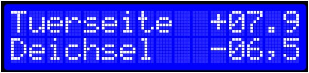
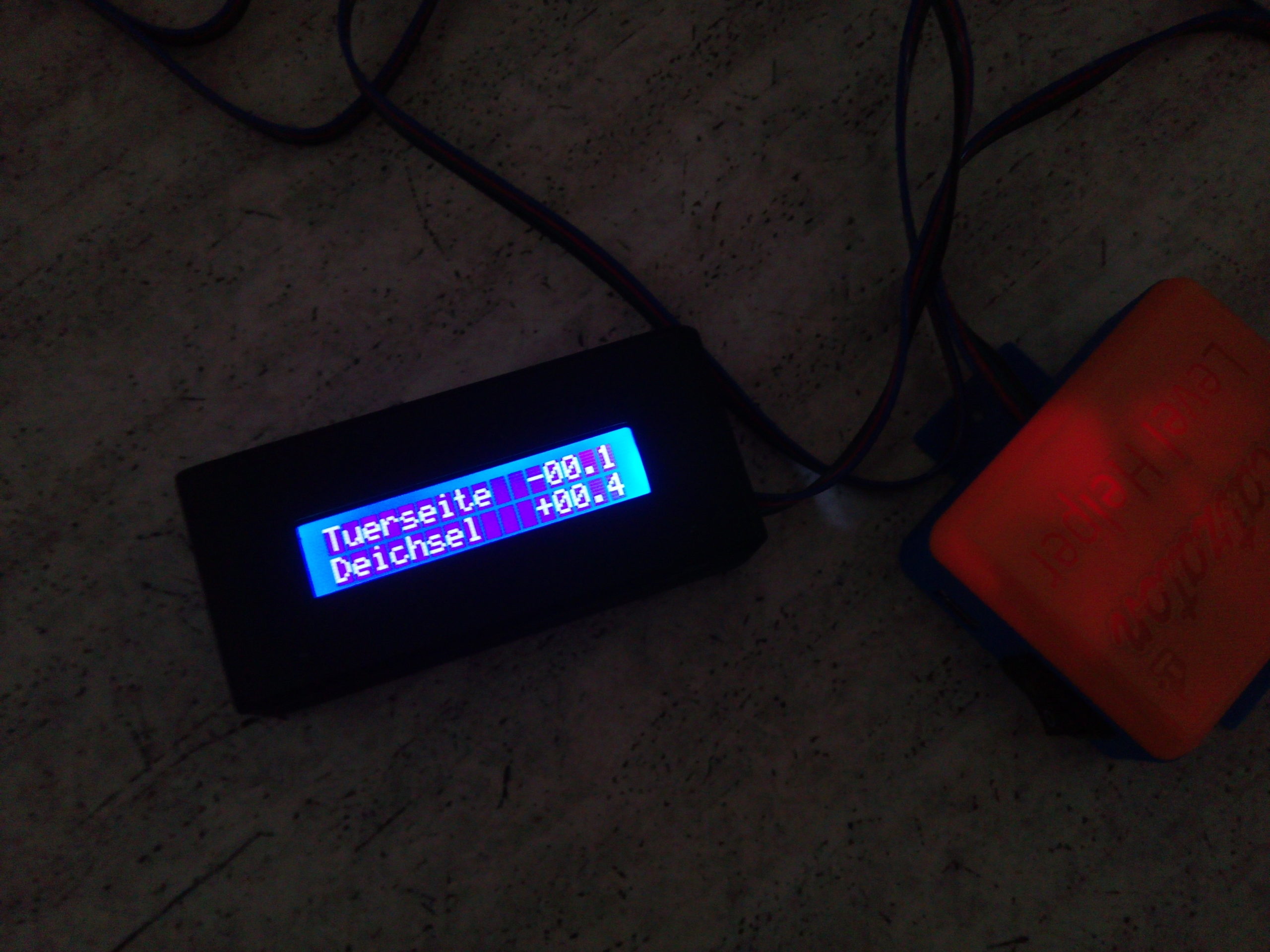
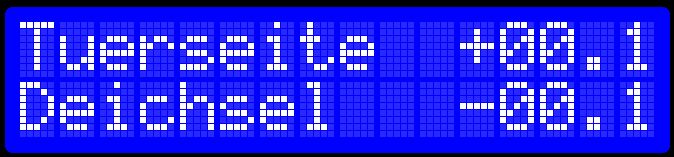
Das Display zeigt nun die jeweilige Neigung in Grad an.
z.B.:
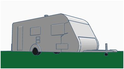
Der Wohnwagen steht auf der rechten Radseite (Türseite) weiter oben als auf der linken Seite, so zeigt euch das Display den Winkel in Grad an.
Für die Achse der Deichsel ist die Ausgabe ebenfalls als Winkel definiert. Im Beispiel ist die Deichsel zu niedrig.

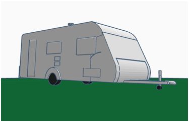
Sind alle Achsen auf Null oder sehr nah bei Null, so ist der Wohnwagen perfekt in Waage und die Stabilisatorfüße können ausgekurbelt werden.
Z.B.
Rohcode http://www.electronoobs.com/eng_arduino_tut76.php
///////////////////////////////////////////////////////////////////////////////////////

/*Terms of use

///////////////////////////////////////////////////////////////////////////////////////

//THE SOFTWARE IS PROVIDED "AS IS", WITHOUT WARRANTY OF ANY KIND, EXPRESS OR

//IMPLIED, INCLUDING BUT NOT LIMITED TO THE WARRANTIES OF MERCHANTABILITY,

//FITNESS FOR A PARTICULAR PURPOSE AND NONINFRINGEMENT. IN NO EVENT SHALL THE

//AUTHORS OR COPYRIGHT HOLDERS BE LIABLE FOR ANY CLAIM, DAMAGES OR OTHER

//LIABILITY, WHETHER IN AN ACTION OF CONTRACT, TORT OR OTHERWISE, ARISING FROM,

//OUT OF OR IN CONNECTION WITH THE SOFTWARE OR THE USE OR OTHER DEALINGS IN

//THE SOFTWARE.
///////////////////////////////////////////////////////////////////////////////////////
//Support
///////////////////////////////////////////////////////////////////////////////////////
Original Code: http://www.brokking.net/imu.html
///////////////////////////////////////////////////////////////////////////////////////
//Connections
///////////////////////////////////////////////////////////////////////////////////////
Power (5V) is provided to the Arduino pro mini by the FTDI programmer
MPU 6050 – Arduino
VCC – 5V
GND – GND
SDA – A4
SCL – A5
LCD 1602 I2C – Arduino
VCC – 5V
GND – GND
SDA – A4
SCL – A5
*//////////////////////////////////////////////////////////////////////////////////////
//Include LCD and I2C library
#include #include
//Declaring some global variables
int gyro_x, gyro_y, gyro_z;
long acc_x, acc_y, acc_z, acc_total_vector;
int temperature;
long gyro_x_cal, gyro_y_cal, gyro_z_cal;
long loop_timer;
int lcd_loop_counter;
float angle_pitch, angle_roll;
int angle_pitch_buffer, angle_roll_buffer;
boolean set_gyro_angles;
float angle_roll_acc, angle_pitch_acc;
float angle_pitch_output, angle_roll_output;
//Initialize the LCD library
LiquidCrystal_I2C lcd(0x27,16,2);
void setup() {
Wire.begin(); //Start I2C as master
//Serial.begin(57600); //Use only for debugging
pinMode(13, OUTPUT); //Set output 13 (LED) as output
setup_mpu_6050_registers(); //Setup the registers of the MPU-6050 (500dfs / +/-8g) and start the gyro
digitalWrite(13, HIGH); //Set digital output 13 high to indicate startup
lcd.init();
lcd.backlight(); //Clear the LCD
lcd.setCursor(0,0); //Set the LCD cursor to position to position 0,0
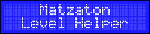
lcd.print(“ Matzaton „); //Print text to screen
lcd.setCursor(0,1); //Set the LCD cursor to position to position 0,1
lcd.print(“ Level Helper „); //Print text to screen
delay(1500); //Delay 1.5 second to display the text
lcd.clear(); //Clear the LCD
lcd.setCursor(0,0); //Set the LCD cursor to position to position 0,0
lcd.print(„Kalibrierung“); //Print text to screen
lcd.setCursor(0,1); //Set the LCD cursor to position to position 0,1
for (int cal_int = 0; cal_int < 2000 ; cal_int ++){ //Run this code 2000 times
if(cal_int % 125 == 0)lcd.print(„~“); //Print a dot on the LCD every 125 readings
read_mpu_6050_data(); //Read the raw acc and gyro data from the MPU-6050
gyro_x_cal += gyro_x; //Add the gyro x-axis offset to the gyro_x_cal variable
gyro_y_cal += gyro_y; //Add the gyro y-axis offset to the gyro_y_cal variable
gyro_z_cal += gyro_z; //Add the gyro z-axis offset to the gyro_z_cal variable
delay(3); //Delay 3us to simulate the 250Hz program loop
}
gyro_x_cal /= 2000; //Divide the gyro_x_cal variable by 2000 to get the avarage offset
gyro_y_cal /= 2000; //Divide the gyro_y_cal variable by 2000 to get the avarage offset
gyro_z_cal /= 2000; //Divide the gyro_z_cal variable by 2000 to get the avarage offset
lcd.clear(); //Clear the LCD
lcd.setCursor(0,0); //Set the LCD cursor to position to position 0,0
lcd.print(„Tuerseite“); //Print text to screen
lcd.setCursor(0,1); //Set the LCD cursor to position to position 0,1
lcd.print(„Deichsel“); //Print text to screen
digitalWrite(13, LOW); //All done, turn the LED off
loop_timer = micros(); //Reset the loop timer
}
void loop(){
read_mpu_6050_data(); //Read the raw acc and gyro data from the MPU-6050
gyro_x -= gyro_x_cal; //Subtract the offset calibration value from the raw gyro_x value
gyro_y -= gyro_y_cal; //Subtract the offset calibration value from the raw gyro_y value
gyro_z -= gyro_z_cal; //Subtract the offset calibration value from the raw gyro_z value
//Gyro angle calculations
//0.0000611 = 1 / (250Hz / 65.5)
angle_pitch += gyro_x * 0.0000611; //Calculate the traveled pitch angle and add this to the angle_pitch variable
angle_roll += gyro_y * 0.0000611; //Calculate the traveled roll angle and add this to the angle_roll variable
//0.000001066 = 0.0000611 * (3.142(PI) / 180degr) The Arduino sin function is in radians
angle_pitch += angle_roll * sin(gyro_z * 0.000001066); //If the IMU has yawed transfer the roll angle to the pitch angel
angle_roll -= angle_pitch * sin(gyro_z * 0.000001066); //If the IMU has yawed transfer the pitch angle to the roll angel
//Accelerometer angle calculations
acc_total_vector = sqrt((acc_x*acc_x)+(acc_y*acc_y)+(acc_z*acc_z)); //Calculate the total accelerometer vector
//57.296 = 1 / (3.142 / 180) The Arduino asin function is in radians
angle_pitch_acc = asin((float)acc_y/acc_total_vector)* 57.296; //Calculate the pitch angle
angle_roll_acc = asin((float)acc_x/acc_total_vector)* -57.296; //Calculate the roll angle
//Place the MPU-6050 spirit level and note the values in the following two lines for calibration
angle_pitch_acc -= 0.0; //Accelerometer calibration value for pitch
angle_roll_acc -= 0.0; //Accelerometer calibration value for roll
if(set_gyro_angles){ //If the IMU is already started
angle_pitch = angle_pitch * 0.9996 + angle_pitch_acc * 0.0004; //Correct the drift of the gyro pitch angle with the accelerometer pitch angle
angle_roll = angle_roll * 0.9996 + angle_roll_acc * 0.0004; //Correct the drift of the gyro roll angle with the accelerometer roll angle
}
else{ //At first start
angle_pitch = angle_pitch_acc; //Set the gyro pitch angle equal to the accelerometer pitch angle
angle_roll = angle_roll_acc; //Set the gyro roll angle equal to the accelerometer roll angle
set_gyro_angles = true; //Set the IMU started flag
}
//To dampen the pitch and roll angles a complementary filter is used
angle_pitch_output = angle_pitch_output * 0.9 + angle_pitch * 0.1; //Take 90% of the output pitch value and add 10% of the raw pitch value
angle_roll_output = angle_roll_output * 0.9 + angle_roll * 0.1; //Take 90% of the output roll value and add 10% of the raw roll value
write_LCD(); //Write the roll and pitch values to the LCD display
while(micros() – loop_timer < 4000); //Wait until the loop_timer reaches 4000us (250Hz) before starting the next loop
loop_timer = micros(); //Reset the loop timer
}
void read_mpu_6050_data(){ //Subroutine for reading the raw gyro and accelerometer data
Wire.beginTransmission(0x68); //Start communicating with the MPU-6050
Wire.write(0x3B); //Send the requested starting register
Wire.endTransmission(); //End the transmission
Wire.requestFrom(0x68,14); //Request 14 bytes from the MPU-6050
while(Wire.available() < 14); //Wait until all the bytes are received
acc_x = Wire.read()<<8|Wire.read(); //Add the low and high byte to the acc_x variable
acc_y = Wire.read()<<8|Wire.read(); //Add the low and high byte to the acc_y variable
acc_z = Wire.read()<<8|Wire.read(); //Add the low and high byte to the acc_z variable
temperature = Wire.read()<<8|Wire.read(); //Add the low and high byte to the temperature variable
gyro_x = Wire.read()<<8|Wire.read(); //Add the low and high byte to the gyro_x variable
gyro_y = Wire.read()<<8|Wire.read(); //Add the low and high byte to the gyro_y variable
gyro_z = Wire.read()<<8|Wire.read(); //Add the low and high byte to the gyro_z variable
}
void write_LCD(){ //Subroutine for writing the LCD
//To get a 250Hz program loop (4us) it’s only possible to write one character per loop
//Writing multiple characters is taking to much time
if(lcd_loop_counter == 14)lcd_loop_counter = 0; //Reset the counter after 14 characters
lcd_loop_counter ++; //Increase the counter
if(lcd_loop_counter == 1){
angle_pitch_buffer = angle_pitch_output * 10; //Buffer the pitch angle because it will change
lcd.setCursor(11,0); //Set the LCD cursor to position to position 0,0
}
if(lcd_loop_counter == 2){
if(angle_pitch_buffer < 0)lcd.print(„+“); //Print – if value is negative
else lcd.print(„-„); //Print + if value is negative
}
//if(lcd_loop_counter == 3)lcd.print(abs(angle_pitch_buffer)/1000); //Print first number
if(lcd_loop_counter == 4)lcd.print((abs(angle_pitch_buffer)/100)%10);//Print second number
if(lcd_loop_counter == 5)lcd.print((abs(angle_pitch_buffer)/10)%10); //Print third number
if(lcd_loop_counter == 6)lcd.print(„.“); //Print decimal point
if(lcd_loop_counter == 7)lcd.print(abs(angle_pitch_buffer)%10); //Print decimal number
if(lcd_loop_counter == 8){
angle_roll_buffer = angle_roll_output * 10;
lcd.setCursor(11,1);
}
if(lcd_loop_counter == 9){
if(angle_roll_buffer < 0)lcd.print(„+“); //Print – if value is negative
else lcd.print(„-„); //Print + if value is negative
}
// if(lcd_loop_counter == 10)lcd.print(abs(angle_roll_buffer)/1000); //Print first number
if(lcd_loop_counter == 11)lcd.print((abs(angle_roll_buffer)/100)%10);//Print second number
if(lcd_loop_counter == 12)lcd.print((abs(angle_roll_buffer)/10)%10); //Print third number
if(lcd_loop_counter == 13)lcd.print(„.“); //Print decimal point
if(lcd_loop_counter == 14)lcd.print(abs(angle_roll_buffer)%10); //Print decimal number
}
void setup_mpu_6050_registers(){
//Activate the MPU-6050
Wire.beginTransmission(0x68); //Start communicating with the MPU-6050
Wire.write(0x6B); //Send the requested starting register
Wire.write(0x00); //Set the requested starting register
Wire.endTransmission(); //End the transmission
//Configure the accelerometer (+/-8g)
Wire.beginTransmission(0x68); //Start communicating with the MPU-6050
Wire.write(0x1C); //Send the requested starting register
Wire.write(0x10); //Set the requested starting register
Wire.endTransmission(); //End the transmission
//Configure the gyro (500dps full scale)
Wire.beginTransmission(0x68); //Start communicating with the MPU-6050
Wire.write(0x1B); //Send the requested starting register
Wire.write(0x08); //Set the requested starting register
Wire.endTransmission(); //End the transmission
}
Das könnte dich ebenfalls interessieren
Wohnwagen Kontrollcenter Arduino

Neue Zugmaschine – Dacia Duster II 2018